
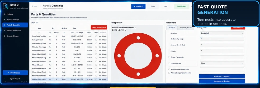
Reliable nesting starts before the optimizer runs. A clean DXF gives the software unambiguous contours, correct dimensions, and the manufacturing rules needed to place each part safely. Poor geometry can create missing holes, duplicate cuts, false parts, incorrect scale, or a layout that cannot be manufactured.
Confirm the drawing units
Compare the imported width and height with a known dimension. Establish one shop standard for inches or millimeters and verify customer files before quoting. A unit mistake can create an obvious scale failure, but smaller discrepancies can still ruin material estimates.
Close exterior contours
The exterior boundary should form one closed path. Tiny gaps can prevent the importer from recognizing a part or cause segments to be treated as unrelated entities. Remove duplicate lines, trim overshoots, and join endpoints within a sensible tolerance.
Open lines may be intentional when they represent bend marks, etching, centerlines, or construction geometry. The important point is to review them rather than silently treating every line as a cutting contour.
Preserve internal holes
Bolt holes, slots, windows, and cutouts belong to the part. They should not be imported as separate loose parts. Verify that each internal contour is closed and located inside the correct exterior boundary.
Usable openings can improve nesting. When manufacturing rules allow it, a smaller part may fit inside a large opening. Nest XL provides part-level control over whether other parts may be placed inside holes.
Remove duplicates and hidden geometry
Duplicate entities can make the machine cut the same path twice. Check for overlapping lines, repeated blocks, hidden layers, zero-length segments, and stray geometry far from the main drawing.
Separate bend and marking lines
Bend lines should be identifiable through a layer, color, linetype, or a deliberate review step. The same applies to engraving and marking operations. A nesting workflow should let the user ignore, preserve, or classify non-cut geometry instead of guessing.
Set orientation intentionally
Rotation affects both material yield and manufacturability. Review fixed orientation, rotation increments, grain direction, surface finish, heat considerations, and long parts that should remain aligned with the sheet.
Use mirroring only when the part allows it. Countersinks, markings, formed features, protective film, and handed assemblies can make a mirrored DXF incorrect.
Enter realistic spacing and margins
The minimum gap depends on the process, material, thickness, heat, kerf, tip-up risk, and shop practice. Extremely small spacing may look efficient while creating unstable cutting conditions. Sheet-edge margins also matter for clamps, damaged edges, and machine limits.
Verify quantities and names
Confirm the required quantity for each part and use recognizable file names. A dense nest is useless if it contains the wrong count. Clear naming improves quote review, production reports, and later project searches.
Review the imported result visually
After import, confirm:
- Exterior shape is complete
- Holes and slots are present
- Dimensions are correct
- Open lines are intentional
- No stray entity enlarged the bounds
- Mirror and rotation settings are correct
- Material and thickness are assigned
Keep the customer's original file unchanged and save a cleaned production copy. Nest XL uses a review-first workflow so the operator approves parts and constraints before nesting begins.